PICkit3 USB Programmer/Debugger

Whether you are a professional embedded systems engineer or some hobbyist and possess a passion for micro controllers, a programmer/debugger is the first thing you need to have. In this tutorial we will be looking t the popular PIC Micro controllers, the Pickit3 Programmer and their interfacing.

Pickit3 is an official programmer and debugger for PIC Micro controllers from Microchip Technologies it can be used with all the PIC Micro controller families using MPLAB ide. Its is a USB based device, so it can be connected to a PC using USB interface while it uses a 6 pin interface with the micro controller to be programmed as shown below.

PICkit3 Pin Configuration:

PIN Signal
1MCLR/Vpp
2VDD (Target)
3VSS (Ground)
4PGD
5PGC
6PGM
MCLR pin stands for Master Clear Reset. So when a LOW pulse is applied to this pin the processor will reset terminating all activities an starting the program from beginning . Normally this pin is connected to a pull up resistor to keep the microcontroller from resetting. PICkit3 uses this pin for resetting the target device.

VDD pin is connected to the power pin of the mcirocontroller also called VDD, This is very important your target device must be connected to it's own power supply, PICkit3 uses the VDD pin to read the voltage level for communication.

VSS pin is connected to micro controller ground, simple as that.

PGD  this must be connected to the PGD pin on the target dvice. This pin serves as connection between the microcontroller and the programmer for data transmission.

PGC pin severs the clock between the PICkit3 and the the corresponding PIC device. It provides the clock signal for synchronized communication.

PGM is Low Voltage Enable Pin (LVP) used for micro controllers with low voltage levels like 3.3v

Hardware Interfacing of PIC and PICkit3


The following diagram shows the necessary connections that must be made between the two devices. Please note the pull up resistor that it must be connected  properly and the resistance values can be 10k or above.


Programming the Micro controller


Now that you have completed the physical connections. It's to burn something to the micrcontroller (I mean to program!). To use PICkit3 as I mentioned earlier you must be using an MPLAB ide with any compiler of your choice like C18, XC8 etc. First make sure that the programmer is connected to the pc and is active, after that go to the MPLAB ide, write your favorite code in it. Before you burn the program, it's a good practice to build the project and see if there are any errors or warnings in the code. After building the project click the "Run Project' (as shown in the figures below) and this will take a few seconds you will see multiple lights blinking and if every thing goes perfect your firmware will be programmed into the microcontroller.

Build You  MPLAB Project


Run the Project to burn the HEX file

Important Notes 


The PICkit3 is an ICSP device which is a protected device so don't worry about conecting the power supply pin of the controller to the chip. The programmer has built in feature of high voltage suppression.

PGM pin as said earlier is used for low voltage programming. So you will mostly leave this pin unconnected in most of the 5v PIC micro controllers as it is a special feature of the PICkit3 for programming the 3.3v logic level micro controllers.

The pull up resistor must be sued with MCLR pin and don't use very low value, as it will draw unnecessary current and will result in degradation in power efficiency.


When it comes to embedded systems, display is an important component either you want the user to have some information or you want your user to better control the system, display is an important part. Display screens comes in different technologies with different dimensions to suit vast needs of embedded systems and the ever growing industry needs, from character display screens to advance graphics rendering screens there is a huge variety.

1602A LCD display with Arduino UNO

In this tutorial we will be looking at interfacing of a 16x2 character display screen with Atmel microcontroller based popular board called Arduino. To be specific we are using 16x2 LCD panel with model no. 1602A (shown in Fig.1) and the board we are using is Arduino UNO(shown in Fig.2).

Fig.1  :   16 X 2 LCD Panel 1602A

Arduino UNO

LCD Pin Configuration


         First thing you need to be familiar with is the pin configuration of LCD panel. The 1602A LCD panel has a total of 16 pins. The following Table shows the pin number with corresponding name and function.
1 VSS The ground pin, this pin must be connected to the common circuit ground
2 VDD The Power Pin this must be connected to the regulated 4.5-5 V regulated supply
3 VO This pin controls the opacity of characters on the LCD screen, connecting it to 5 V will give you block of dots instead of character, on the other side connecting it to the ground will make the opacity of characters 0 and the characters will not visible.
4 RS Register select pin. When RS=0 Command register is selected, when RS=1 Data register is selected
5 RW Read/Write selection bit. When RW=0 LCD registers can be read, when RW=1 LCD registers will be available to receive data.
6 E Enable pin. This pin controls the entire operation of LCD whether it's write operation or read operation.
7 D0 1st bit of Data/Command byte
8 D1 2nd bit of Data/Command byte
9 D2 3rd bit of Data/Command byte
10 D3 4th bit of Data/Command byte
11 D4 5th bit of Data/Command byte
12 D5 6th bit of Data/Command byte
13 D6 7th bit of Data/Command byte
14 D7 8th bit of Data/Command byte
15 A/LED+ The brightness control pin. This pin controls the brightness if the LCD screen, connecting it to the +5v will give the full brightness while connecting to ground will cause the back lite of the LCD to turn off. This is mostly connected to +5 V through a low value resistor (e.g. 330 ohms)
16 K/LED- Must be connected to ground

LCD Interfacing Protocol


Before we move on with the arduino board and LCD 1602A it should be good to have the knowledge of the procedure or more precisely the protocol of the LCD interfacing The arduino UnO board uses the 4bit- interfacing with the LCD out of two interfaces i.e. 8-bit mode and 4-bit mode. Although as along as you are using Arduino UNO with LCD panel you don't need to know about it, anyways if you are interested you can read the following tutorial

Protocol of interfacing a 16x2 LCD to microcontrollers.


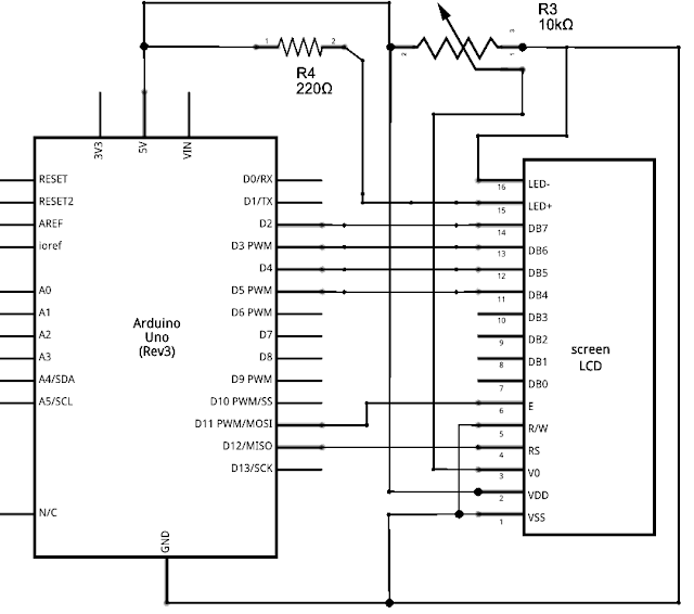
Arduino and 1602A LCD Wiring Diagram


LCD Hardware Interfacing with Arduino


Ok so now let's get started to the practical implementation of this circuit. As said before we will be using Arduino UNO, but need not alarmed you can use any other arduino board they all support the LCD interfacing with more or less same connection and the code.

first connect your LCD panel to the arduino board as shown in the following diagram.

So your final circuit should look something like this
Arduino LCD interfacing Circuit diagram

To avoid any mistakes look closely to the circuit and connect your board with the LCD screen carefully.

Arduino Code


Now that we have completed our system physically, it's time to write some code. We will use official arduino ide for developing firmware for the board.
The entire code is actually very short and simple because luckily arduino handles most of the things in the background.


#include <LiquidCrystal.h>
           // initialize the library with the numbers of the interface pins
LiquidCrystal lcd(12, 11, 5, 4, 3, 2);
void setup() {
          // set up the LCD's number of columns and rows:
  lcd.begin(16, 2);
          // Print a message to the LCD.
  lcd.print("I Am Legend!");
}
void loop() {
         // set the cursor to column 0, line 1
         // (note: line 1 is the second row, since counting begins with 0):
  lcd.setCursor(0, 1);
         // print the number of seconds since reset:
  lcd.print(millis() / 1000);
}


The first line of the code is essential, it just includes the builtin in LCD library of arduino. 
In the second line we initialize the library by telling it the pin connections. The first two parameters of the function lcd function are the respective pin numbers of the RS and E pin. If you are thinking about RW pin, it's not connected to the arduino but connected directly to ground.
Now in setup section first we begin lcd operation by using function begin which takes two parameters, columns and rows of the LCD respectively.  In the next line the magic happens we print a string by using function print.
In the loop module of the code we choose the write position on 2nd row and 1st column and print the number of seconds passed since we started the board.
Now compile the code, if everything goes right you should see something on the screen like in the top figure.


Important Notes :


  • RW pin must be connected to ground.
  • VO pin must be connected to a voltage in between 0 - 5v or else none of the characters will be displayed and then you will be finding out "Why my lcd is not working with arduino? "